CAD for Prosthetics
In my previous post, I mentioned doing a medical collaboration for a prosthesis project of sorts.
Now, the business side of this project was very disappointing and I eventually pulled out of the gig, but am happy with the takeaways I got from it. And here I am to tell the tale of how the technical side of this collaboration went.
Design scope
Before starting the actual modeling process, we had to agree on what the scope should be. In short, the prosthetic coved had to:
- be very light and durable (as in, able to withstand physical impact as well as environmental changes over long periods of time)
- easy to put on or swap
- consist of a front and back part
- cover the full volume around the center pole of the prosthesis
- have minimal contact points with the prosthesis
- not rub against the lower part of the prosthesis socket
- not come in contact with any nuts, bolts, or screws
- accommodate for any custom made parts of the prosthesis, like vacuum clamps
- the lower part of the front panel had to be extended a bit more and curve outward
- the lower part of the back panel had to be cut at an angle, so it doesn’t interfere with the spring mechanism around the heel area
- mimic the natural shape of a human leg
The last point was quite tricky because a near perfect shape can only be done with a 3D scanner. This still wouldn’t be the perfect solution, though, because 3D scanners are iffy, not always dimensionally accurate, and scanned files always require a lot of model clean up before they can be used further.
The basic shape
I decided to do most of the modeling in Fusion 360, since this is the app I’m mostly familiar with. It’s not the best solution for organic modeling, but I’d rather have a decent looking model that fits, than a great looking model that’s not dimensionally accurate.
A note on aesthetics and trying to make things realistic
It goes without saying that people are very different in anatomy, and this also applies to calfs. The calf consists of three different muscle groups and the development of each gives a unique shape/twist to the overall structure of the leg.
Depending on their age and physical condition, BK amputees might have gone through a significant amount of muscle atrophy on both their legs, resulting in a more slender and streamlined calf shape. To keep things simple, I didn’t want to overdo the curved shape, and decided to go for a design that’s more symmetrical and can be applied to either leg.
Lofts - the answer to most CAD problems, the Universe in general, and everything in between
Lofting is one of the most versatile tools in 3D design. You just sketch a bunch of shapes on a 3D plane, and applying a loft creates a body that’s the volume constrained between these sketches. It’s very similar to a regular extrusion, but gives you the ability to create very complex shapes - both geometric and organic.
Here’s a quick example - this shape starts off as a circle, but morphs into an octagon towards its top.

I only had a handful of measurements to work with - the overall height of the prosthesis and the circumference of the top and bottom part of the leg. I also had the diameter of the center pole of the prosthesis, and a rough measurement of the socket base. Those were first set in my base sketch and were then overlapped with a reference image I applied on top, resized it to match the scale, and eyeballed the rest of the curve.
Here it is:
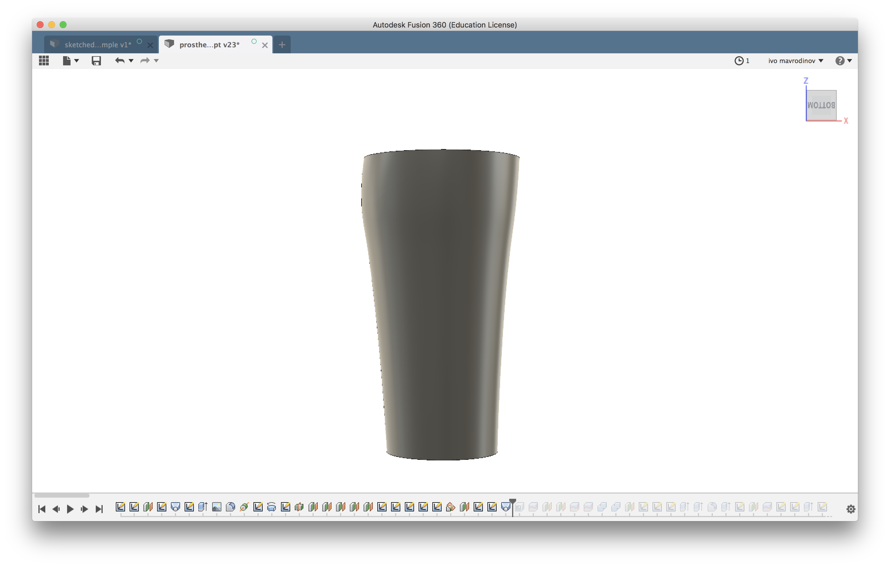
I then went ahead and shelled (hollowed) it, and split it lengthwise. To ensure this would be easy to 3D print, I set the shell thickness to be a multitude of the nozzle diameter of my printer. Five perimeters should do it (2mm thickness using a standard 400 μm nozzle).
It didn’t make any sense to keep the top and bottom part of each piece, so I got rid of them and was left with a cylindrical body that’s split in two.
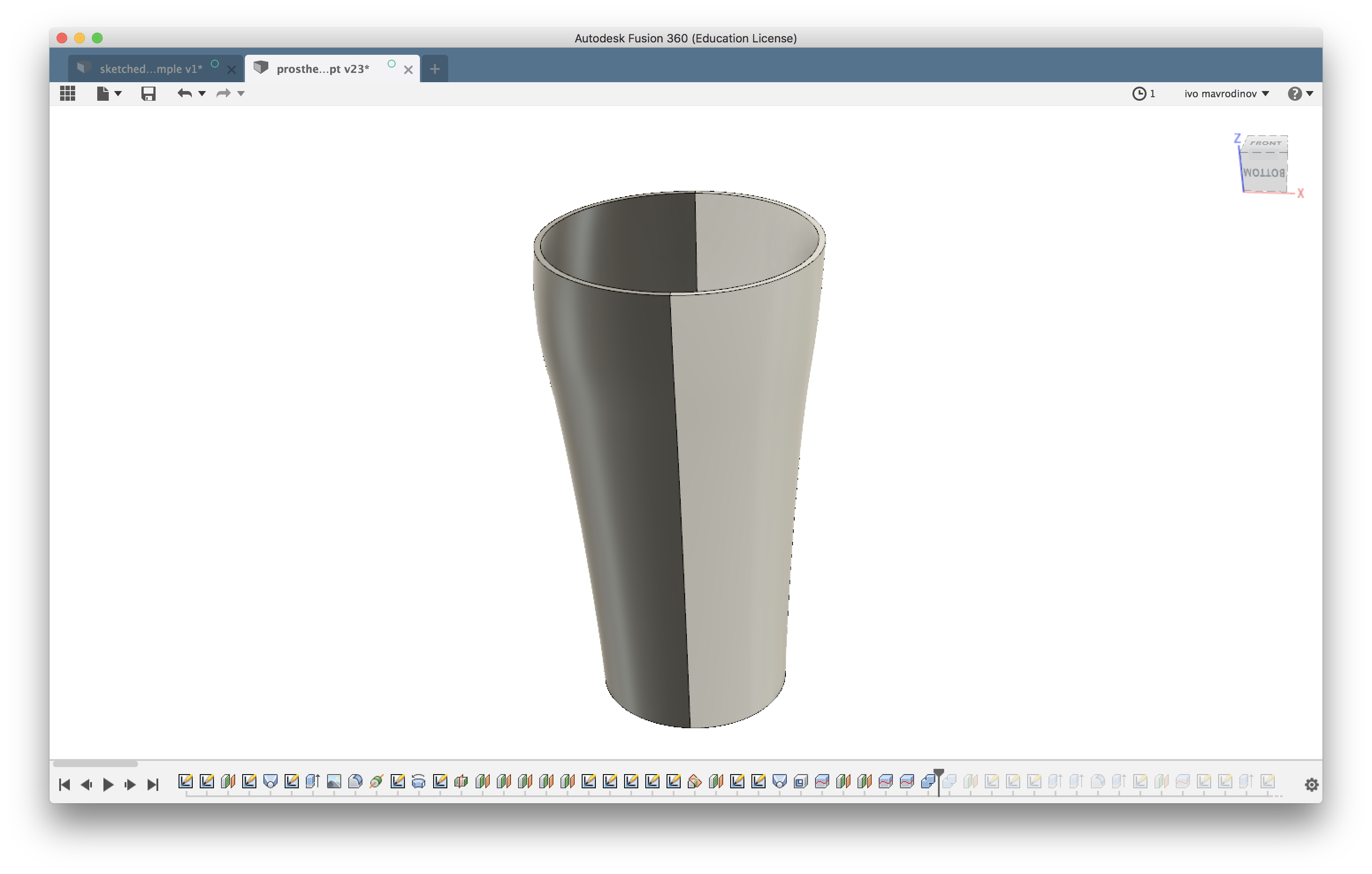
So far so good. This got me to a point where I have a workable foundation that’s easy to shape further.
One task down, three more to go.
PS: It should be easy to achieve a more accurate and natural curvature by adding more sketches to the loft. I went with two based on the scarce measurements given, but here’s a quick example showing a better attempt. The example sketch below consists of twelve offset planes, one inch apart. Each layer has a center diameter circle with a radius equal to the side-to-side caliper measurement of my own leg at that point, and the oval dimension is the shin-bone-to-calf measurement:
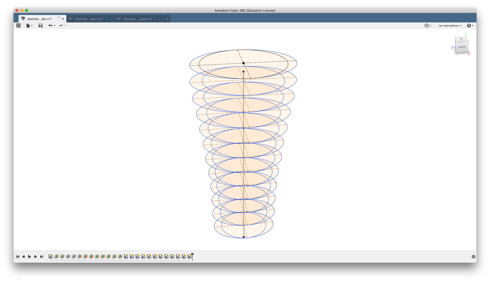
To loft this sketch, select the center circle and one of the crescents on each offset plane.
Next were the joints
I had to think of a way to reliably attach the back panel to the prosthesis, and this turned out trickier than expected. One joint would probably not do, because it might not provide sufficient stability. Decided to go for two similar ones with a slight offset in between.
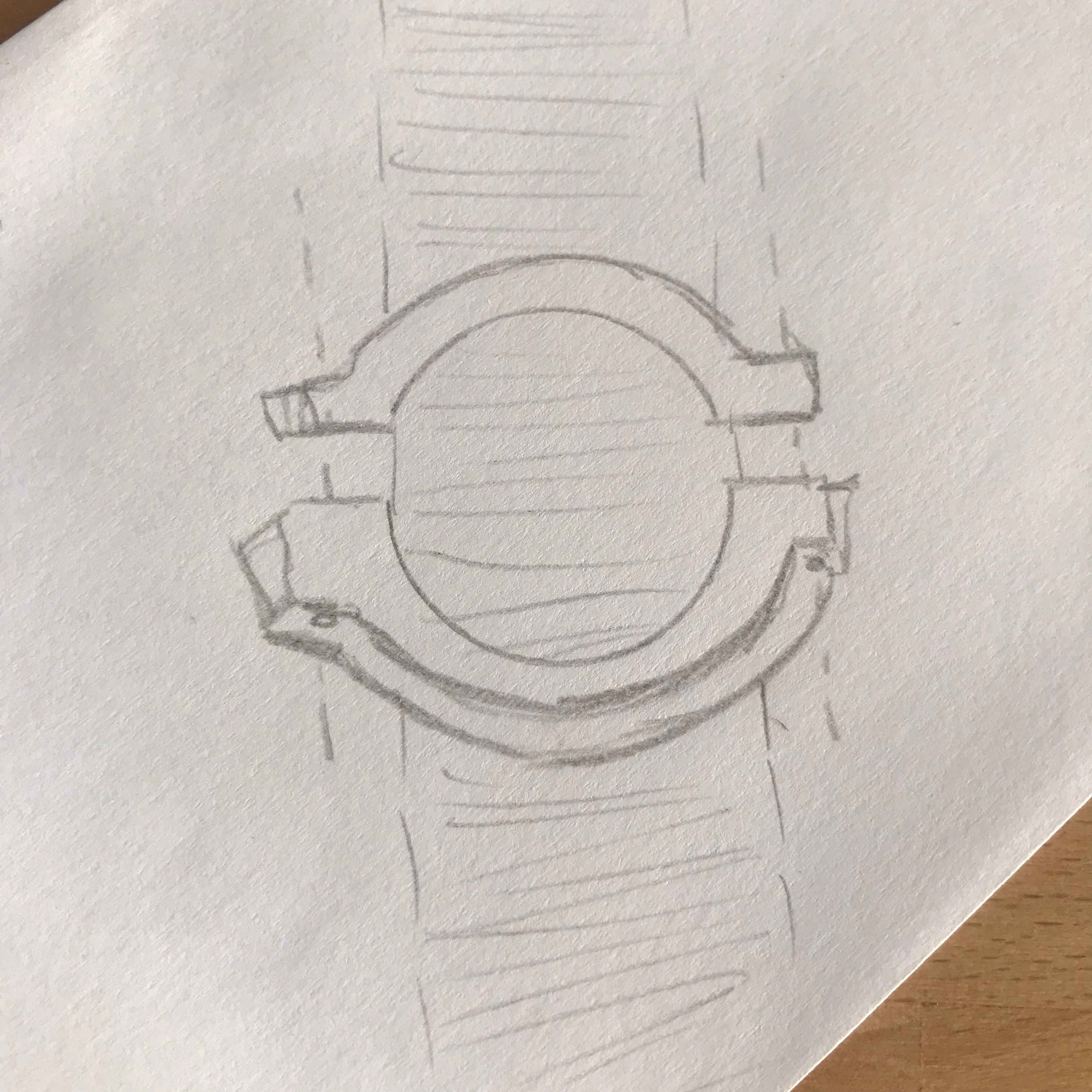
My first stab at this was a clip that can be slid through the center prosthesis pole and then tightened down with bolts. Not the best approach, because the component looked bulky and would also not work well if printed using non-flexible materials.
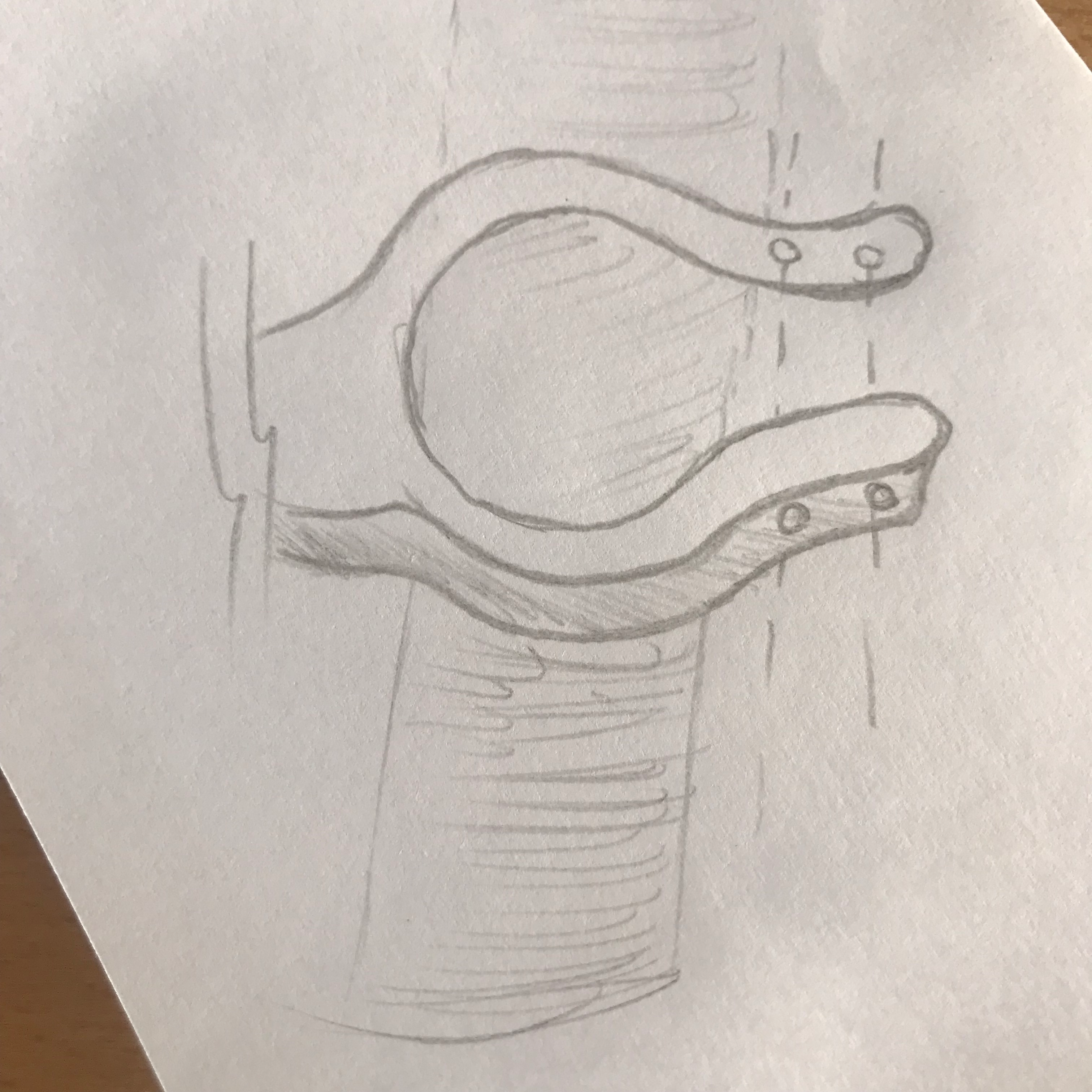
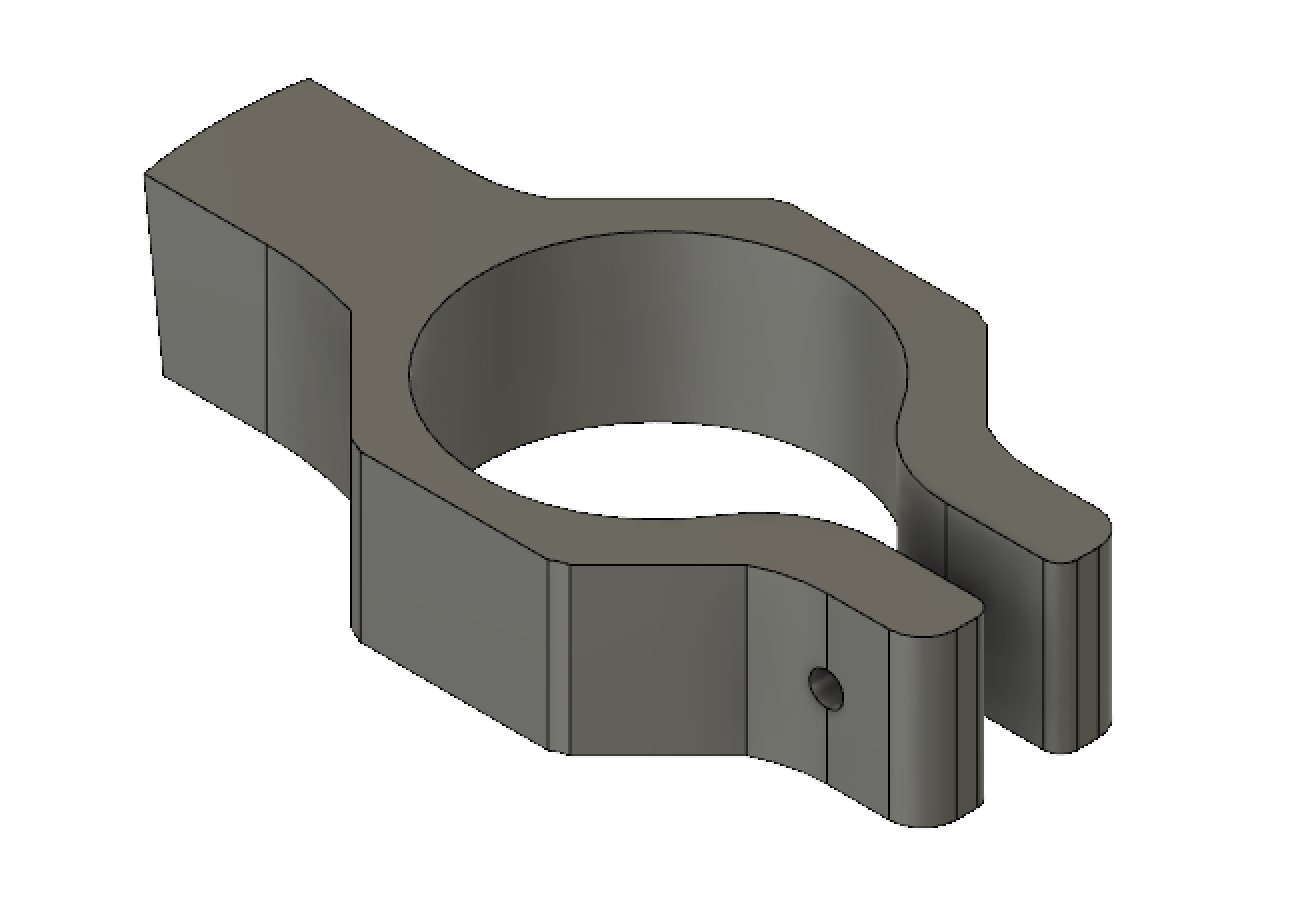
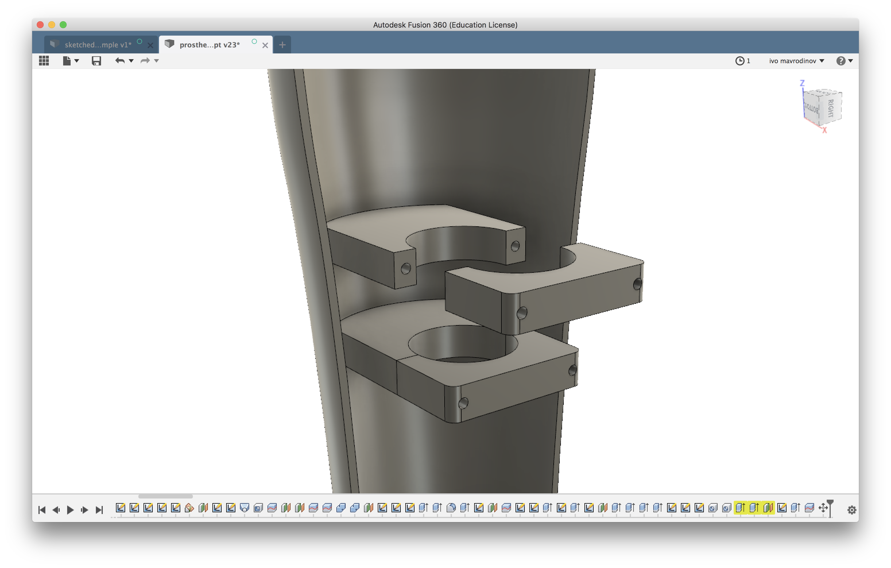
My second take was much more simple and efficient - a two piece clamp that can be tightened around the center pole with screws. The overall footprint is much easier to 3D print, requires less cleanup from support material, and can be tightened down to guarantee a secure fit.
So I went with this idea and created two clamps one inch apart from one another. This would make sure that the back panel won’t wobble around and hold tight to the rest of the assembly.
There’s nothing special about the clamps - they were sketched on a center offset plane between both shell pieces, then extruded and joined up to the back panel. Done and done.
Both shells should snap fit together
At this point, I had the main cover body mostly done, and had a way of securely attaching it to the prosthesis. Almost every design like this goes the magnet route, so I followed.
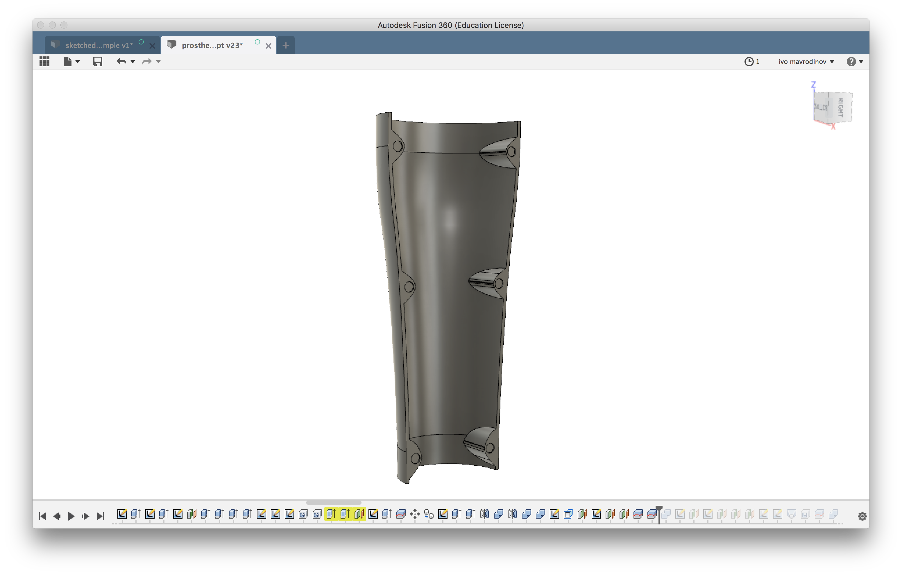
Adding magnet slots to the existing body was fairly straightforward. I sketched three wing shaped curves on each side of the back cover, extruded them inward, and punched holes to fit 6mm cylindrical magnets with a 0.2 mm tolerance to fit epoxy filler. These six extrusions were created as separate bodies on purpose, and were then mirror-copied to the front panel.
The total length of two connected magnets is 10 mm, but it’s not equally split between both panels. The front shell has shallower slots, while the ones on the back piece are much deeper. This way, when both panels snap fit together, the magnet links are within the back piece and can’t be accidentally separated.
Design
With modeling mostly done, it was time to come up with a design of some sort.
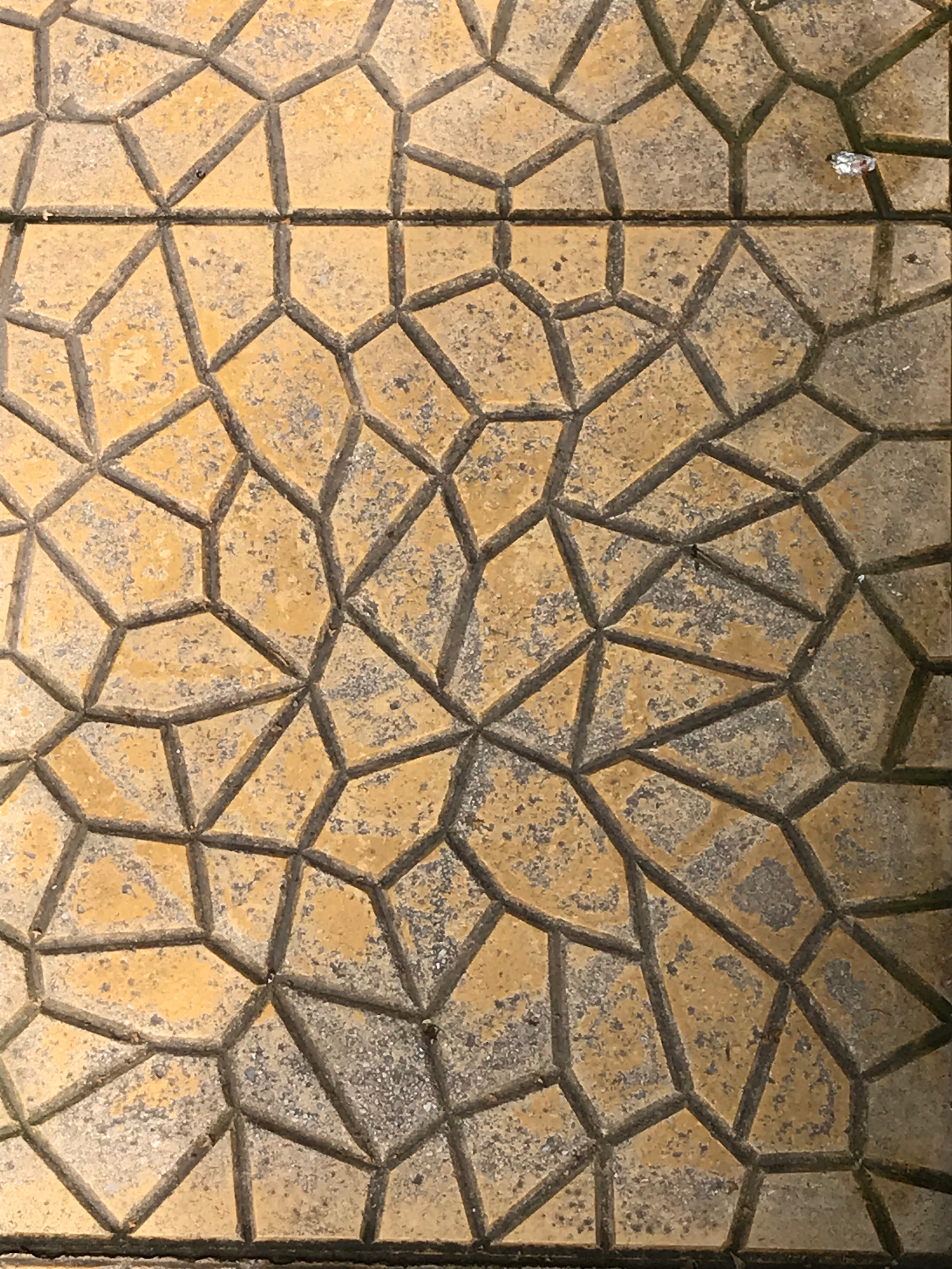
Apart from looking good, the main idea of adding some kind of design was to reduce the overall weight of the product. Voronoi tessellations are widely considered catchy, so I wanted to use them on the front panel.
This Fusion plugin was giving me really bad results, so I ditched it and tried sketching a few shapes on my own. This didn’t work either, so I ended up using a picture of a broken tile as reference.
Fusion doesn’t have any dedicated tools for doing this sort of design work, and I didn’t want to spend too much time trying to get it perfect either.
To get the pattern on my model, I created a new offset plane, attached the reference image to it, traced parts of the design, and then extruded them through the front panel to make the cuts.
Here’s the final result:
Also, I was too lazy to properly loop this gif.
Filament research
Looping back to the first point on our scope, I had to do some research on what kind of 3D printing filament would be appropriate for this kind of application.
It had to be really strong, but also have some flex to it. Other than that, it had to be heat resistant and not degrade over prolonged exposure to UV.
PLA, ABS, PETG and some of their derivatives are out of the question - none of the three would be of any use beyond printing a prototype of the model.
ASA - it’s like ABS, but less horrible
Dubbed the go to filament for outdoor use, ASA is very similar to ABS in structure, but far less annoying to work with.
I got a roll from Sweden’s Prima Select shop and ran it through a few test prints. Looks like a nozzle temperature of around 240 works well, with the bed set to 90 and the part cooling fan either off, or left on 10% speed.
Unlike ABS, ASA doesn’t delaminate during printing, but using an enclosure to keep drafts and cold air out is still recommended.
ASA has the highest UV resistance of all mainstream filaments, meaning printed parts will not become brittle or crack after being outdoor for extended periods of time.
Nylon - a miracle material (if you know how to tame it)
Nylon has been on my filament list for a really long time, and I finally got a couple of rolls from Taulman for this project.
Nylon is a co-polymer that’s being used in a variety of different fields because of its high strength and flexibility, excellent chemical resistance and overall durability.
There are over a dozen different types of nylon derivatives, and the ones I got are Bridge and PCTPE. The latter is a nylon-polycarbonate blend that seems a bit easier to print with, but still has one annoying property all filaments of this kind have - water absorption.
Wet filament tends to pop, ooze, and result in uneven extrusion lines regardless of how slow it’s being printed. The only way to alleviate this is baking the whole roll of nylon in an over at low heat for a few hours. The thing is, I don’t have an oven at home, and the kitchen hot pot is not large enough to fit the filament spool.
Until I figure out a way to dehumidify my rolls of nylon, I did my final test prototype in PLA to ensure the model fits correctly.
Further development
Spending some tine on this project was a huge learning experience for me. I got to design something that looks sleek and has a high degree of dimensional accuracy, got to try out a few exotic filaments, and also spent some time exploring a new business idea.
The project is far from being done, so I plan to revisit it sometime next year and see how much of the design I can open source. This should be possible thanks to Fusion’s parametric design variables. They’ll make it fairly simple for anyone to get the basic shape right, but getting the design pattern right would still require manual work.